
Automobile headlamp mirror injection mold strength and parting surface pipe position design
Automobile headlight reflector (also known as reflector) is a part of automobile headlight lighting system that has the function of reflection to avoid direct light. It is located inside the lens and decorative frame and assembled with the lens. Through the lens, the reflector can be seen from the outside of the vehicle light.Plastic parts for appearance, surface aluminum plating, belongs to the high - light electroplating parts, the surface has a large area of decorative surface.The lamp is an essential safety device and decorative part for the automobile. Due to the high temperature working environment and the reflective concentrating effect of the reflector, the prefabricated integral mold plastic (BMC) thermosetting plastic with a shrinkage rate of almost 0, heat resistance, flame retardancy and strong creep resistance is needed for shaping.This material used to die casting molding process, due to low production efficiency, high rejection rate, at the same time, because the material is harmful to human body, the production of die casting need to be frequent manual material weighing procedures, so the health of operators to bring a certain risk.Therefore, it has become an inevitable trend to develop injection molding technology of BMC material instead of die casting molding technology.
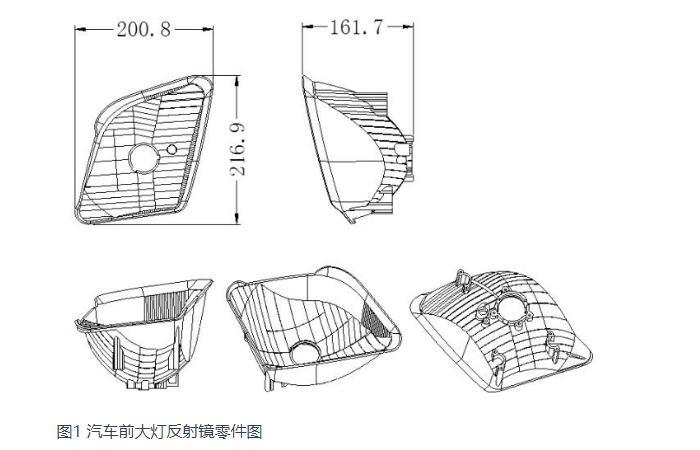
This paper takes the automobile headlight mirror parts as an example and introduces the design key points and technical summary of the injection mold of automobile headlight mirror.Auto headlight reflector parts are shown in Figure 1:
1. Appearance requirements and structural analysis of plastic parts
Figure 1 shows the parts drawing of a certain brand of automobile headlamp reflector. The material is BMC, which belongs to thermosetting plastic.The material is a special hard material, the shrinkage rate is almost zero, there is no need for the shrinkage rate in the mold design.Because it is especially hard plastic, with high dimensional precision, good processing performance and other advantages, the disadvantage is poor liquidity.The outer surface of the plastic parts should be electroplated (generally aluminum plating). The plastic parts are external parts with high surface requirements.
The size of plastic parts is 216.9×200.8×161.7mm.The structural features of the plastic parts are as follows:
1) The appearance is highly required. No spots or gate marks are allowed on the surface, and no shrinkage dents, weld marks, flying edges and other defects are allowed.
2) The plastic parts are electroplated, with strict requirements for light distribution and aluminum plating on the surface.Appearance demodulation slope design to be reasonable, generally at least to ensure that more than 5°.
3) The shape of the plastic parts is complex, with high surface finish. There is no inverted inside and outside of the plastic parts, and lateral core pulling is not required. The plastic parts are left and right mirror images.
2. BMC material injection molding process
The refrigerated BMC material is added to the barrel of an injection molding machine specializing in THE production of BMC material, which is melted at a low temperature (25 ° C) by rotating the screw to produce shear heat, and then the thick gelatine material is injected at high pressure into a mold preheated to 140-160 ° C.Under the action of high temperature, chemical reaction is carried out. After curing and forming, the molded parts are taken out after opening. Finally, the burr and debris in the mold cavity are blown out with an air gun, and the mold is closed for the next cycle.
3. Mold structure analysis
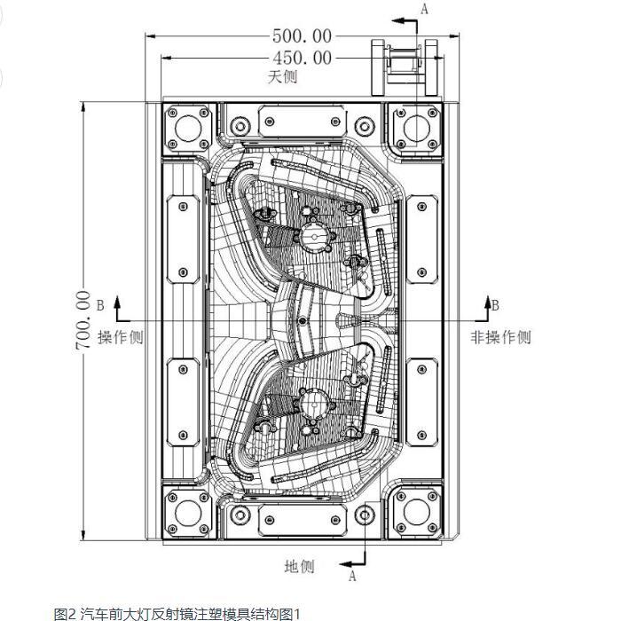
The mirrors of automobile headlamps are left and right mirror images, and the number of cavities is 1+1. The casting system of cold runner is adopted in the mold.There is no upside down inside and outside of the plastic parts, so there is no side core-pulling mechanism.The mold's external size is 700×500×568 (mm), and its total weight is about 1 ton. It is a medium-sized injection mold.See Figure 2- Figure 4 for the detailed structure.
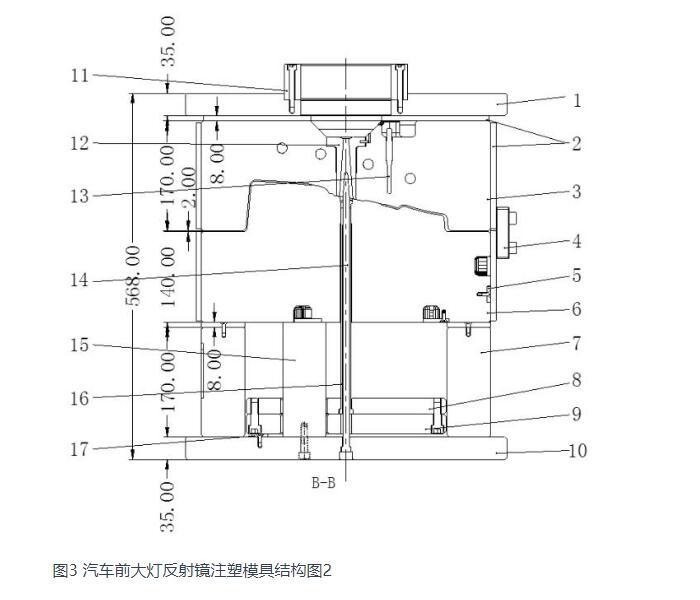
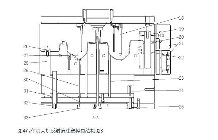
1. Panel;2. Heat shield;3. A plate;4. Lock module;5. Line pressing block;6. B board;7. The iron;8. Push rod fixing plate;9. Push rod bottom plate;10. The base plate;11. Positioning ring;12. The machine's mouth;13. Temperature needle;14. Push tube needle;Support column; 15.16. The ejector sleeve;17. Garbage nails;Heating tube 19. Guide post;Pressure plate; 20.21. Protection block of junction box;22. The guide bush;23. The push rod;24. Limit block;25. Reset;26. Fast reset;27. Moving die inserts;28. Reset lever;Push pipe sleeve; 29.Push tube needle; 30.31. Push rod plate guide sleeve;Push rod plate guide post; 32.33. Push tube needle press block;
Figure 2, Figure 3 and Figure 4 are the mold structure drawings of automobile headlight reflector.Although its basic structure is similar to that of the thermoplastic injection mold, compared with the latter, it has the following typical differences and characteristics:
(1) Reverse mold
The die mentioned here is not inverted die.General mold cavity in fixed mold, mold core in moving mold.Because the mirror plastic core is multi-surface reflection and concentrated light working face, need very low roughness, absolutely cannot set push rod and other ejector device, so the mold must be reversed, that is, the convex core (mirror working face) is set in the fixed mold, the concave cavity is set in the moving mold.
(2) The mold shall be heated by a heating tube and the temperature shall be strictly controlled
The injection molding process of BMC material is completely different from that of ordinary thermoplastic injection molding process. The injection molding machine barrel part needs to be cooled by special refrigerating machine ice water, while the mold cavity core needs to be electrically heated.
The following formula can be used to calculate the total power W of the electric heat pipe required by the fixed mode:
W=Gcp(Tm-To)/3600yt
G: The total weight of the fixed die,kg
Cp: Specific heat capacity of mold material, KJ /(kg.°C)
Tm: Temperature required for mold forming: °C
To: Room temperature: °C
Y: Heater efficiency, 0.3-0.5
T: Heating time, h.
Generally, the diameter of the electric heat pipe is 15.8mm, which can improve the mold temperature quickly.According to experience, the heating power of die can be calculated according to (40-50) W/kg.The forming surface of the plastic part is 40-50mm away from the electric heat pipe, and the distance between the two electric heat pipes is 80-100mm.In order to improve the heating efficiency, an 8mm thick bakelwood heat insulation board shall be designed for all sides of the fixed mold. Since the electric heat pipe has no positive and negative poles, it can be connected in series, but each set of temperature controller socket shall not exceed 3.6kW.The temperature of each set of electric heat pipe is controlled by a set of thermocouples. The thermocouple should be in the center of the temperature field of this set of electric heat pipe, and the thermocouple head should be in effective contact with the mold cavity, which is conducive to accurate temperature control.
(3) Mold runner system needs to control temperature
Since the material formed by thermosetting injection mold starts to solidify by chemical cross-linking reaction when it exceeds a certain temperature, the solidified pouring system can only be used as waste material instead of recovery, so it is of great significance to adopt the flow path without the solidified pouring system.Therefore, the sprue sleeve of the mold should be cooled with cold water.In order to reduce excessive shear heat generated during injection molding and improve injection molding speed, fan-shaped diverter channels are generally set in moving molds with a gate thickness of 2.0-2.5mm so as to prevent molten BMC material from curing before filling high temperature cavities.
(4) Requirements for mold parting surface
The viscosity of BMC material is lower than that of thermoplastics. No holes or pits are allowed on the parting surface. The sliding block locking block and pressing block are not allowed to be set at the die core, otherwise it will cause the problem of flash cleaning.
(5) The exhaust of mold cavity needs to be strengthened
Ordinary thermoplastic plastic molding is a physical change process, and thermosetting plastic injection molding is a chemical reaction process, chemical reaction will produce a large number of volatile gas, these gases will produce a lot of resistance to injection molding, resulting in plastic surface bubbles and lack of materials, at the same time the gas compression produced by high temperature burning plastic parts.Therefore, it is particularly important to exhaust the mold cavity of thermosetting injection molding. In general, the parting surface of the mold and the bottom of the insert of the fixed mold shall be equipped with high-temperature sealing ring, and the end of the feed flow of the fixed mold cavity shall be vacuated to overcome the forming defects, which is also convenient to improve the injection speed.
(6) High precision of plastic parts
The light distribution of the reflector is very high, and the roughness of the reflector, machining and assembling precision are very high.In addition to the edge lock of mould blank and the positioning of guide post, it is also necessary to design the positioning of mould kernel stop to ensure the reliable three-stage positioning of the mould.The polyhedron has a small area of light distribution grain, so manual polishing cannot be carried out. Precision five-axis high-speed CNC machining machine must be adopted, and the spindle speed of the machine tool can reach more than 20000 RPM.Adopt advanced CAM technology and special cutting tools, choose reasonable processing technology, one processing in place.Cavity precision is required to be 0.01-0.02mm, cavity surface roughness is 0.05-0.10 micron.
3.1 Design of forming parts
The molding parts and template of this mold adopt integral body, commonly known as the original body.Compared with the split-type structure, its advantages are compact structure, good strength and rigidity, small mold volume, and avoid the cumbersome procedures such as opening frame, matching frame and manufacturing inclined wedge.
The inner surface of the headlamp reflector is required to be very high, and the roughness is small. Thimble and inlay marks are not allowed, so it must be molded by fixed mold. The outer surface has relatively low requirements and is molded by moving mold.
This plastic part is one of the most important exterior parts of automobile, and it is a high-gloss part, the surface needs vacuum electroplating.In the design of this mold, we must first pay attention to the selection of mold materials.Due to poor flutility of BMC material, overflow tank needs to be designed around the moving template cavity, and push rod needs to be designed at the bottom of the overflow tank to facilitate the discharge, as shown in FIG. 11.The BMC thermosetting material is filled with glass fiber, and the mold needs to have high wear resistance, hot red hardness, heat resistance and fatigue.Due to the strict light distribution requirements of the mirror, the core should have good polishing performance.Therefore, the mold fixing material USES German 2344ESR hot tool steel with excellent hardenability, quenching hardness of 48 ~ 52HRC.The steel material remelted by vacuum electroslag improves the crystal uniformity of steel and the polishing effect is excellent.The fixed mold is often polished by hard chromium plating to reduce surface roughness, improve wear resistance and prevent corrosion.Moving mold, moving mold inserts are made of German 2344HT hot tool steel, quenching hardness of 48 ~ 52HRC.
The insertion Angle of the fixed die on the insertion part of this mold is guaranteed to be above 7 degrees at least. In order to ensure the accurate positioning of the fixed die, the fixed die adopts the positioning of the four-angle stop and the surrounding edges.Due to the need for accurate positioning at the insertion place, the fixed die needs to be tightly matched when fitting the die. In order to make the die beautiful and match the mold, a 5-degree wear-resisting block is designed in the fixed die, so as to avoid the occurrence of ugly grinding of the mold by the fitter.At the same time, wear-resistant block design, convenient fitter mold matching, to ensure the beauty of the mold.
This mold design also achieved the following points:
1) The parting surface is smooth without sharp Angle, thin steel, wireless or point sealant;The surface sealing adhesive is constructed, and the surface method such as extension, sweep and mesh is used in the parting. The parting surface is constructed according to the shape of the plastic part. The parting surface of the vehicle lamp mold is highly required, and the wrinkling of the constructed surface is not allowed.The parting surface constructed can effectively ensure CNC machining accuracy, without EDM Angle cleaning, parting surface is not easy to run burr.High speed machine is needed when the auto lamp mould parting surface polishing tool, and the spindle speed of the machine tool is guaranteed to be above 20000 RPM at least.
2) The fitting part of insert and moving die is designed with appropriate technology of turning R Angle or avoiding vacancy at the end of the stop, which simplifies the processing procedure and reduces the processing time to improve the processing efficiency.
3) Design R angles of all non-forming corners to prevent stress cracking. Process R angles shall be no less than R5. Design a relatively large process R Angle as far as possible according to mold size;Sharp edges on the mold are easy to cause accidental injury to the operator. The edges that are not involved in forming or cooperating should be designed with C or R angles, and a larger chamfer should be designed as far as possible according to the size of the mold.
4) Avoidance of parting surface: The width of parting surface is 40MM, and 1MM should be avoided for the fixed die in the area outside parting surface, so as to effectively reduce processing time.The avoidance of parting surface not only refers to the peripheral parting surface, but also includes large area parting surface.Special note: the width of the parting face of the die includes the exhaust slot.The pressure block should be designed in the large area of space to ensure the uniform force of the mold, to avoid the mold from running in the long term production. When the perforated area of the mold is designed to avoid the air, the exhaust hole should be designed in the fixed or moving mold to facilitate the discharge of compressed air when the fixed or moving mold is closed.
5) The parting surface shall be constructed according to the shape of the plastic parts, and the plastic parts shall be optimized when necessary.For medium and large mold, pressure plate groove should be opened as far as possible to facilitate CNC machining.When designing parting surface, try to simplify mold processing and make it smooth and smooth. The parting surface is made without thin steel, sharp Angle and reasonable insertion Angle.
6) The parting surface is smooth and flat, and it is forbidden to have many small broken surfaces when UG parting (CNC machining is easy to snap and the machining accuracy is reduced). Try to use extension surface, mesh surface and sweep surface to build the parting surface, or first extend 10-20mm glue sealing surface, then make stretch surface and transition surface, and the glue sealing surface is designed according to the tonnage of injection molding machine and the size of mold.
7) The parting surface or all the piercing angles shall be designed above 7 degrees to improve the service life of the mold.
3.2 Gating system design
The mold casting system adopts "ordinary runner + fan-shaped gate".Because the plastic part is BMC material, the flow is poor, when designing the runner, the runner should be thick and short.In order to reduce excessive shear heat generated during injection molding and improve injection molding speed, fan-shaped diverter channels are generally set in moving molds with a gate thickness of 2.0-2.5mm so as to prevent molten BMC material from curing before filling high temperature cavities.
3.3 Design of temperature control system
Automobile headlight reflector is one of the most important exterior parts of automobile and also one of the plastic parts with the highest appearance requirements. Therefore, the design of temperature control system has a great influence on the molding cycle and product forming quality of the mold.Because the plastic parts are made of BMC material, the injection molding process of BMC material is completely different from that of ordinary thermoplastic injection molding process. The injection molding machine barrel part needs to be cooled by special refrigerating machine ice water, while the mold cavity core needs electric heating.
The layout of heating pipes is similar to that of waterways and Wells, and can be designed as vertical layout or horizontal layout.The forming surface of the plastic part is 40-50mm away from the electric heat pipe, and the distance between the two electric heat pipes is 80-100mm.In order to improve the heating efficiency, an 8mm thick bakelwood heat insulation board shall be designed for all sides of the fixed mold. Since the electric heat pipe has no positive and negative poles, it can be connected in series, but each set of temperature controller socket shall not exceed 3.6kW.The temperature of each set of electric heat pipe is controlled by a set of thermocouples. The thermocouple should be in the center of the temperature field of this set of electric heat pipe, and the thermocouple head should be in effective contact with the mold cavity, which is conducive to accurate temperature control.See Figures 5 and 6.
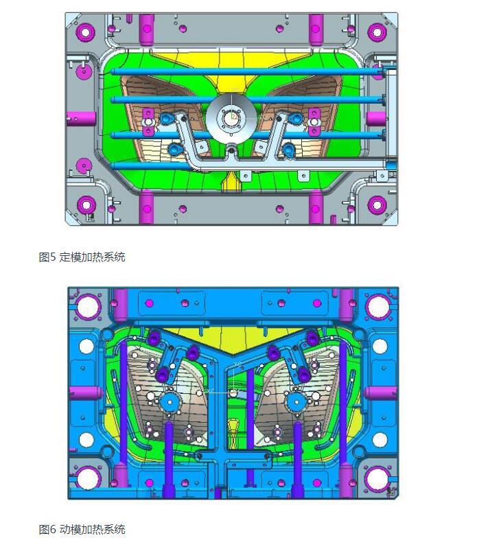
The temperature control system of this mold is as follows: 2 vertical heating pipes are designed for each hole of the mold, and 4 horizontal heating pipes are set for the mold.Three vertical heating tubes and two horizontal heating tubes are designed for each cavity of the moving mold.Attention should be paid to the arrangement of heating pipes, and the corners of the pipes should be rounded to avoid damaging the lines.A temperature probe shall be designed for each mold, and the spacing of the heating tubes shall be uniform. The heating tubes shall be ordered from the supplier. The hole of the heating tube shall be 1mm larger than the heating tube and the depth shall be 1mm deeper, because the heating tube will expand during heating.
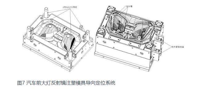
3.4 Design of guiding positioning system
This mold has designed a D40*225 round guide pillar at each of the four corners.(Guide column can be up to 10 times diameter) The guide column is installed on the fixed mold side. Since the plastic parts remain on the moving mold side after opening the mold, it will not affect the plastic parts to take out, and avoid the plastic parts sticking to the guide column oil.
The guide column can also be used as a supporting foot to FIT the die when turning over the die, as shown in Figure 7.The length of the circular guide column must be ensured when closing the mold, insert the guide sleeve 20mm before the oblique guide column is inserted into the slider, otherwise it will bring great trouble in the mold manufacturing and production, and the mold will be seriously damaged.The design of the die guide system must pay attention to the design of the three-level positioning, especially for the automotive plastic parts with high requirements.It is the most important system of injection mold that the mold movement is not smooth, the mold is easy to be damaged, the fixed mold is out of position, and the parts are in different stages.
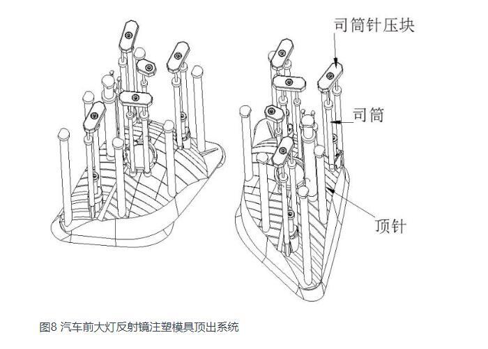
The ejector pin (i.e., push rod) is the extrusion structure of the mold. After the fixed and moving molds are opened, the ejector piece and the flow passage solidifier are pushed out by the push rod.There is no need to add a reduction spring next to the four reduction rods, but the reduction block 26 should be designed at the fixed template position in contact with it. The material is S50C, and the surface is nitrified.
The following points should be paid attention to when designing the mold release system:
1) The push rod plate guide column shall be arranged near the push out element with large push out force (such as oil cylinder).Reset lever, etc.).
2) All auto injection molds shall be designed with limit posts, which shall be arranged above or near the K.O hole in priority.
3) The putter shall be arranged in the stress position near R and arranged in the position with high binding force. For BMC thermosetting materials, the putter shall be designed in large specifications with a large number of putter to ensure ejection balance.This is because the BMC plastic parts are very hard, the clamping force of the mold is larger, and the required top output is also larger.
4) Try to adopt the same size and specification when designing the diameter of push rod, so as to avoid frequent change of drill bit and save processing time and cost.
5) All shaped surface putter must design stop rotation, and avoid wrong assembly, and sai grid on the putter surface, and avoid slipping when pushing out.
6) The return pinhole is designed with empty holes on one side (0.5 for small and medium-sized molds and 1.0 for large molds), and the return pin end is designed with screw holes.In order to facilitate the processing and clamping, when the diameter of the return needle is greater than or equal to 20MM, the return block should be designed for the surface.The ejector hole of injection molding machine should not interfere with the garbage nail and support column.
3.6 Design of mold structure parts
4 D40*225 guide posts are used to guide and support the mold. The overall strength of the mold is good.In the process of injection molding, due to the impact of injection pressure, the strength of the template will be affected to some extent.Therefore, in addition to sufficient strength of the mold, some auxiliary structural parts need to be designed to enhance the strength and life of the mold.
The following points should be noted in the design:
1) in order to FIT and convenient processing, this mould thimble between floor and code template design four screws, screw specification to be larger than thimble screw plate specifications, beside the process screw carved "process screw", because the technology of screw in the mold production is to dismantle, the purpose of this design is to facilitate fitter to identify, prevent to make mistakes.The limit posts should be arranged above or near the KO hole as far as possible, and more garbage nails should be arranged at the bottom or near the inclined top and straight top, with an interval of about 150mm.
2) The pressure block on the parting surface of the mold sinks into the mold. The pressure block and precise positioning shall not be used for oil grooves. The distance between the pressure block slot and the edge of the mold frame shall be at least 15mm.
3) Design of limit column: The mechanical ejecting mold is designed above the ejecting rod hole;The die for the cylinder ejecting is designed above or near the cylinder.
4) Support column design: The distance between the support column and the square iron should be 25-30mm, and the distance between the support column and the support column should be 80-120mm.The total area of the support column is 25%-30% of the area of the fixed plate of the push rod.1. Multiple support columns should be designed in the glue feeding area and the projected area of plastic parts, and the support column should be designed as large as possible.Because injection pressure is concentrated in these areas, the parting surface is prone to flaps, so multiple design supports can reduce the appearance of parting surface and runner flaps.2. Support heads shall be arranged at the positions with weak strength, such as the bottom of the slider and the bottom of the inner core pulling.
5) Garbage nails must be designed at the bottom of the return pin (garbage nails are designed on the bottom plate);If the ejector system consists of two plates, screw fastening must be designed near the return pin to avoid ejector plate deformation.
4. Mold working process
Melt by injection molding machine nozzle, the machine mouth 12 into the mold cavity, the melt filled cavity, the pressure maintaining and cooling and solidification, and after enough rigidity, injection molding machine pull mold fixed board 10, moving die from parting surface PL Ⅰ mould.Mould of 300 mm, injection molding machine oil cylinder push push a fixed plate 8, push a fixed plate driven push rod, 28, injection oil cylinder to continue to function, then out after 70 mm, plastic parts and mould separation, plastic parts after manipulator pick-up, injection molding machine oil cylinder push pull a fixed plate and reset, then promote dynamic injection molding mould clamping, mould began the next injection molding.
5. Design of mold strength and parting surface pipe position
The parting face of this mold is designed on the fixed die, with the design form of combining the four corners and the four sides, so that the positioning is reliable and the strength of the mold is good.In the automobile mold design, the Angle of the fixed moving die inserted as far as possible to design more than 7 degrees, it is not enough to design more than 5 degrees.Because the insertion Angle is large, the life of the die will be greatly increased, and the phenomenon of the die at the insertion point will be greatly reduced.For the positions with the insertion Angle below 3 degrees, 1 degree precision positioning and 0 degree precision positioning are difficult to ensure the accurate positioning of the fixed die, so the insertion Angle should be as large as possible. For large and medium-sized molds, the design is generally above 7 degrees, so as to ensure the service life of the die.
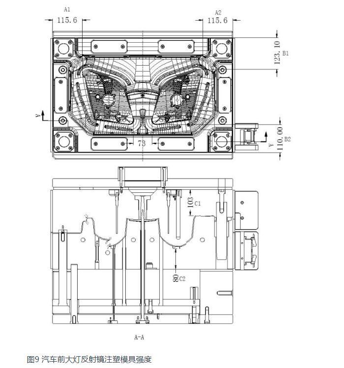
The main dimensions that affect the strength and rigidity of the die include:
1) Dimensions A1, A2, B1 and B2 from cavity edge to mold edge;
2) The distance C1 and C2 from the deepest part of the impression to the bottom of the fixed and moving template, as shown in Figure 10.
In automobile mold design, the empirical determination method of dimensions A and B is as follows:
1) If there is no lateral core-pulling mechanism, add 30mm ~ 50mm sealant size from the outermost edge of the mold cavity (30mm for small molds within 5050, 40mm for medium molds within 5050 ~ 1010, and 50mm for large molds above 1010), and then add 50mm ~ 70mm to avoid vacancy, so as to reduce the workload of mold matching.Avoid vacancy is also to ensure the strength of the mold area.Then, the dimensions of the pressure plate on the face of the die frame are A and B.
2) If there is A side core-pulling mechanism, the dimensions A and B shall be increased according to the core-pulling distance. In principle, the slider must remain in the template after core-pulling.
For plastic parts of different sizes and structures, the value of mold size C will be different. Size C must ensure that the deepest part of the mold cavity is more than 80mm steel thickness to the bottom of the formwork. In dynamic formwork, because there is empty between two square iron pieces, it is easy to be deformed after bearing the injection pressure, so C1 shall be correspondingly increased in thickness, generally taking more than 100mm.
Because this mold has two cavities, the two cavities are symmetrical, A1=A2=115.6mm, and the distance between the left mirror and the right mirror cavity is 73mm.Since the mold has no side core-pulling mechanism, B1=123.1mm, B2=110mm.In terms of thickness and size, C1=103mm, C2=80mm, and B plate appears to be a little thinner. Try to design it around 100mm.
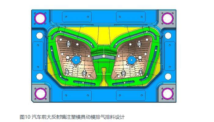
6. Die exhaust system and discharge design
Ordinary thermoplastic plastic molding is a physical change process, and thermosetting plastic injection molding is a chemical reaction process, chemical reaction will produce a large number of volatile gas, these gases will produce a lot of resistance to injection molding, resulting in plastic surface bubbles and lack of materials, at the same time the gas compression produced by high temperature burning plastic parts.Therefore, it is particularly important to exhaust the mold cavity of thermosetting injection molding. In general, the parting surface of the mold and the bottom of the insert of the fixed mold shall be equipped with high-temperature sealing ring, and the end of the feed flow of the fixed mold cavity shall be vacuated to overcome the forming defects, which is also convenient to improve the injection speed.The moving die of this mould USES the clearance between insert and moving die.BMC has poor fluidness, and overflow tank needs to be designed around the moving model cavity. Thimble needs to be designed at the bottom of the overflow tank to facilitate the discharge, as shown in FIG. 10.
For the automobile lamp mirror mold, the main design points are as follows:
1) Special injection molding process equipment is required, and BMC plastic injection molding machine is adopted, which has very strict requirements on injection molding process equipment.
2) BMC material belongs to extra-hard plastic. In the mold design, heating system and parting surface design discharging system should be designed. The molded parts must be quenched to improve wear resistance and mold life.
3) The reflection mirror plastic parts on the car lights is to prevent direct light, light reflection and avoid direct light device, light distribution requirements are strict. Plastic parts for the car's most important appearance, plastic parts have a lot of patterns on the surface is to play a decorative aesthetic effect.
4) The ejecting system of BMC material mold design should be balanced, and the size of push rod should be designed as large as possible, and the number should be as large as possible, otherwise it will cause the mold disassembly difficulty.
5) Because is the high light electroplating part demodulation Angle is too small will cause demodulation difficult, so the mirror plastic side wall demodulation Angle design as far as possible, the general recommendation in 5° ~ 10°. Of course, the premise is not to affect the function and shape of plastic parts.
6) The plastic parts should not have sharp corners, and all corners should be designed into rounded corners, because the forming parts of the mold are prone to stress cracking after quenching.
7) Note the left and right mirror cap hole and plastic surface pattern is translation, can not be designed into mirror symmetry, because the bulb and lamp cap will not be divided into left and right, the rest of the features are mirror symmetry.